In this article, we will study about the Fourier transform analysis or Fourier Transform in Circuit Analysis. The Fourier transform is basically a mathematical operation that decomposes a signal into its constituent frequency components. In simple words, it converts a signal from the time domain to the frequency domain. The time domain will represent the signal as a function of time, while the frequency domain represents the signal as a function of frequency.
Fourier Transform
The Fourier transform is an amazing powerful tool for analyzing the behavior of different kinds of circuits, as it allows us to see how the circuit responds at different frequencies. This is useful for different kind of tasks, such as:
- Analyzing the response of a circuit to arbitrary input signals: This can be easily used to design circuits that can handle a huge range of input signals, such as audio signals or video signals.
- Identifying the resonant frequencies of a circuit: Resonant frequencies are the frequencies at which a circuit will amplify the signals. This information can be used to design the circuits that should operate at specific frequencies, like as filters or oscillators.
- Designing filters to remove unwanted frequency components from a signal: Filters can be mostly used to remove the noise or interference from a signal, or to extract specific frequency components from a particular signal.
- Understanding the stability of a circuit: A stable circuit is one that will simply not oscillate or diverge. The Fourier transform can be used to analyze the stability of a circuit by just looking at the frequency response of the circuit.
The Fourier transform is also used in many other fields, including signal processing, image processing, and quantum mechanics.
In this article, we will discuss the following topics that are related to the Fourier transform in circuit analysis:
- Types of Fourier transforms
- Properties of the Fourier transform
- Applications of the Fourier transform in circuit analysis
We will also discuss the examples as well as illustrations to help in understanding the concepts in a proper manner.
Understanding the Reason of Evolution
The Fourier transform was first developed by the well known French mathematician Jean-Baptiste Joseph Fourier in the early 19th century. He was deeply interested in solving the equation of heat conduction, which is a partial differential equation. Fourier realized is that he could solve the equation by simply decomposing the initial temperature distribution into its constituent sine and the cosine waves.
The Fourier transform has since been applied to a large range of problems in the physics and engineering, which include circuit analysis. In the circuit analysis, Fourier transform can be used to analyze the response of a circuit to an arbitrary input signals.
Effects of Fourier Transform
The Fourier transform has a large number of important effects on circuit analysis. In that first, it allows us to analyze the response of a circuit to arbitrary input signals. Then second, it allows us to identify the resonant frequencies of a circuit. After that in third, it allows us to design filters use to remove unwanted frequency components from a signal.
Fourier Transform Formula
The Fourier transform of a signal x(t) is denoted by the X(f) and is defined as follows:
X(f) = \int_{-\infty}^{\infty} x(t) e^{-j2\pi ft} dt
Here f is the frequency in parameter of Hertz.
The notation used in the Fourier transform formula is:
- x(t) is an time-domain signal.
- X(f) is the frequency-domain signal.
- j is a imaginary unit.
- e −j2πft is an complex exponential function.
Types of Fourier Transform
There are mainly two types of Fourier transforms:
- Continuous Fourier transform (CFT)
- Discrete Fourier transform (DFT).
Continuous Fourier Transform (CFT)
The CFT is defined for continuous-time signals, which are basically a signals that can take on any value at any time.
The continuous Fourier transform (CFT) of a signal x(t) can be defined as follows:
X(f) = \int_{-\infty}^{\infty} x(t) e^{-j2\pi ft} dt
where f is the frequency in Hertz.
Notation that used in the CFT formula is:
- x(t) is the time-domain signal.
- X(f) is the frequency-domain signal.
- j is the imaginary unit.
- e −j2πft is the complex exponential function.
Derivation of the CFT
The CFT can be easily derived from the Fourier series of an periodic signal. The Fourier series of a periodic signal x(t) with period T is given by:
x(t) = \sum_{n=-\infty}^{\infty} c_n e^{j2\pi n\frac{t}{T}}
Here Cn are the Fourier coefficients of the signal.
The CFT can be obtained by simply taking the limit of the Fourier series as the period T approaches to the infinity. In this limit, the Fourier coefficients become a continuous functions of frequency, and the Fourier series becomes the CFT.
Discrete Fourier transform (DFT)
The DFT is defined for discrete-time signals, which are a signals that can only take on certain values at specific certain times.
The discrete Fourier transform (DFT) of a discrete-time signal x[n] can be defined as follows:
X[k] = \sum_{n=0}^{N-1} x[n] e^{-j2\pi kn/N}
Here k is the frequency index and N is the length of the particular signal signal.
Notation that used in the DFT formula is:
- x[n] is the discrete-time signal.
- X[k] is the frequency-domain signal.
- j is the imaginary unit.
- e −j2πkn/N
- is the complex exponential function.
Derivation of the DFT
In simple terms CFT is basically defined for continuous-time signals, while the DFT is defined for discrete-time signals. The DFT is mostly used the type of Fourier transform in circuit analysis, as most electronic circuits which operate on discrete-time signals.
The DFT of a discrete-time signal x[n] is denoted by the X[k] and is defined as follows:
X[k] = \sum_{n=0}^{N-1} x[n] e^{-j2\pi kn/N}
Here k is the frequency index and the N is the length of the signal.
The DFT can be derived from the CFT by simply sampling the CFT at discrete frequencies:
X[k] = X(f = k/N)
Examples of Fourier Transform with Diagram
Let’s consider the following example circuit:
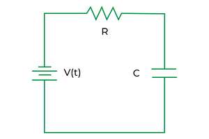
Simple RC Circuit
Here the input to the circuit is a square wave, and the output is an filtered square wave. Where the Fourier transform of the input square wave is a series of impulses at the harmonic frequencies. The Fourier transform of the output square wave is a series of attenuated impulses at the harmonic frequencies.
Here are the following diagram which shows the Fourier transforms of the input and output signals:

Fourier Transform Input Output
Properties
The Fourier transform has a number of important properties, that including the :
- The Fourier transform of a real signal is conjugate symmetric.
- The Fourier transform of a linear combination of signals is a linear combination of the Fourier transforms of the individual signals.
- The Fourier transform of a time-shifted signal is a frequency-shifted signal.
- The Fourier transform of a frequency-shifted signal is a time-shifted signal.
Characteristics
The Fourier transform of a signal has these following characteristics:
- The magnitude of the Fourier transform of a signal will represents the amplitude of the frequency components of the signal.
- The phase of the Fourier transform of a signal will represents the phase of the frequency components of the signal.
Applications
The Fourier transform has a huge number of applications in circuit analysis, that include:
- Analyzing the given response of a circuit to arbitrary input signals.
- Identifying the resonant frequencies of a circuit.
- Designing filters to remove the unwanted frequency components from a signal.
Advantages and Disadvantages
Some of the advantages and disadvantages of of Fourier Transform are-
Advantages:
- The Fourier transform is a most powerful tool for analyzing the frequency response of an circuits.
- It can be used to design filters to remove unwanted frequency components from a signal.
Disadvantages:
- The Fourier transform can be much more complex to understand and use too.
- The Fourier transform can be computationally more expensive to calculate.
Difference Between Laplace Transform and Fourier Transform
Basically the Fourier transform is mostly similar to the Laplace transform, but there are a few key differences. In that the Fourier transform is defined for continuous-time signals, mean while the Laplace transform is defined for both the continuous-time and discrete-time signals. Additionally, the Fourier transform is not a well-suited for analyzing transient signals, while the Laplace transform is useful in it.
|
Domain
|
Time and frequency
|
Frequency only
|
|
Definition
|
X(s)=∫
−∞
∞
x(t)e
−st
dt
|
X(f)=∫
−∞
∞
x(t)e
−j2πft
dt
|
|
Applications
|
Circuit analysis, signal processing, control theory
|
Circuit analysis, signal processing, image processing, quantum mechanics
|
Forward and Inverse Fourier Transform
The forward Fourier transform can converts a signal from the time domain to the frequency domain. The inverse Fourier transform should converts a signal from the frequency domain to the time domain.
The inverse Fourier transform is defined as follows:
x(t) = \int_{-\infty}^{\infty} X(f) e^{j2\pi ft} df
Forward Sine Transform and Fourier Cosine Transform
The forward sine transform and the forward cosine transform are basically two variants of the Fourier transform. The forward sine transform is defined as follows:
S(f) = \int_{-\infty}^{\infty} x(t) sin(2\pi ft) dt
The forward cosine transform is defined as follows:
C(f) = \int_{-\infty}^{\infty} x(t) cos(2\pi ft) dt
The forward sine transform and forward cosine transform are very useful for analyzing signals with the even and odd symmetry, respectively.
Conclusion
Overall the Fourier transform is an most essential tool for circuit to analysis. It provides us the permission to understand how circuits respond to different frequencies, which is more essential for designing and the analyzing electronic circuits. The Fourier transform has a different kind of applications in circuit analysis, including analyzing the response of a circuit to arbitrary input signals, identifying the resonant frequencies of a given circuit, designing filters to remove unwanted frequency components from the signal , and understanding the stability of a circuit.
The Fourier transform is also used in many of other fields, that includes the signal processing, image processing, and the quantum mechanics. It is a very versatile and powerful tool with wide range of applications.
Here are some additional mindful thoughts on the importance of the Fourier transform in circuit analysis:
- The Fourier transform simply allows us to analyze linear and nonlinear circuits.
- The Fourier transform can be used to analyze different kind of circuits in the time domain or the frequency domain.
- The Fourier transform can be used for analyze circuits with multiple inputs and the outputs.
- The Fourier transform can be used to analyze circuits with the feedback loops.
The Fourier transform is an powerful tool that can be used to analyze a wide range of circuit problems. It is an essential tool for any circuit engineer.
Frequently Asked Questions
1. What is the difference between the Fourier transform and the Laplace transform?
The Laplace use for both CFT and DFT but not Fourier transform
2. Why is the Fourier transform important in circuit analysis?
The Fourier transform is more important in circuit analysis just because it allows us to analyze the frequency response of circuits. The frequency response
3. What are some applications of the Fourier transform in circuit analysis?
The Fourier transform can be used for a variety of tasks in circuit analysis, such as:
Analyzing the response of a circuit to arbitrary input signals.
Identifying the resonant frequencies of a circuit.
Designing filters to remove unwanted frequency components from a signal.
Understanding the stability of a circuit.
Please Login to comment...