Ampere’s Circuital Law and Problems on It
Last Updated :
04 Mar, 2022
André-Marie Ampere, a French physicist, proposed Ampere’s Circuital Law. Ampere was born in Lyon, France, on January 20, 1775. His father educated him at home, and he showed an affinity for mathematics at a young age. Ampere was a mathematician and physicist best known for his work on electrodynamics, Ampere’s Law, and the confirmation and amplification of Oersted’s work on the relationship between electricity and magnetism.
He was also the inventor of the astatic needle, which is a key component of the modern astatic galvanometer. He was the first to show that a magnetic field is formed when two parallel wires are charged with electricity. He is widely regarded as one of the pioneers in the field of electromagnetic. The ‘ampere,’ a unit of electric current, is named after him.
Ampere’s Circuital law
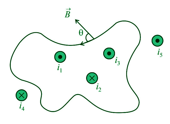
“Around every closed curve, the line integral of the magnetic field B is equal to μ0 times the net current I threading through the region contained by the curve.”
i.e.
∮B’dl’ = μ0∑i = μ0(i1+i3–i2)
where,
μ0 denotes the permeability of empty space and B denotes the magnetic field at a location on the surface’s boundary that forms an angle ” with the length element ‘dl’.
The ‘Amperian loop’ is also known as the sum of all the B’dl’ products across the whole loop.
Note:
- (i1+i3–i2) is the total current that crosses the above loop. Any current beyond the region is not included in net current, but we must include the magnetic field owing to all currents when calculating B’dl’ (both inside as well as outside the loop currents)
- Sign convention: (positive outward current, negative inward current)
- This rule only applies to stable currents. This law stays true regardless of the size and shape of the current-enclosing closed route (Amperian loop).
- The phrase B’dl’=0 does not imply that the magnetic field B is zero everywhere along the path, but it does imply that no net current is travelling through it.
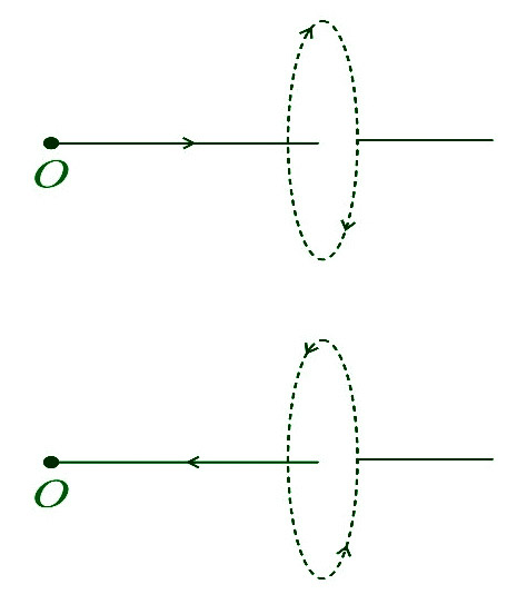
- The closed path’s direction is clockwise when the stream is flowing away from the observer. The closed route is anticlockwise when the current is flowing in the direction of the observer.
Alternative Form of Ampere’s Circuital Law
We know that,
∮B’dl’=μ0∑i=μ0(i1+i3–i2)
By using B’=μ0H’ (where H= magnetizing field)
∮B’dl’=μ0∑i=μ0(i1+i3–i2)
∮μ0H’.dl’=μ0Σi
∮H’.dl’=Σi
Inconsistency of Ampere’s Circuital Law
Ampere’s Law is only applicable for constant current or when the electric field does not vary with time, according to James Clerk Maxwell. Consider a parallel plate capacitor being charged by a battery to demonstrate the discrepancy. Time-varying current travels across connected wires during charging.
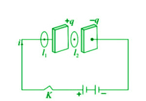
Applying Ampere’s Law for loop l1 and l2
For loop 1− ∮l1B’⋅dl’=μ0i
For loop 2− ∮l2B’⋅dl’=0 (i=0 between the plates).
However, it is noticed that a magnetic field exists between the plates when they are charged or discharged in practice. As a result, Ampere’s Law fails.
i.e.
∮l1B’⋅dl’≠μ0i.
Modified Ampere’s Circuital Law or Ampere – Maxwell’s Circuital Law
During the charging process, Maxwell hypothesized that some current must travel between the capacitor plates. It was given the term displacement current by him. As a result, the updated law is as follows:
∮ B’⋅dl’=μ0(ic+id)
or
∮B’⋅dl’=μ0(ic+ε0 x dϕE/dt)
where;
ic= Conduction current = current due to flow of charges in a conductor and
id= Displacement current =ε0 x dϕE/dt= current due to the changing electric field between the plates of the capacitor.
Note:
- The magnitude of the displacement current (id) equals the size of the conduction current (ic).
- The total of ic and id in a circuit is always continuous, even if they are not continuous.
Application of Ampere’s Circuital Law
The law of Ampere is applied.
- The magnetic field produced by a cylindrical wire must be determined.
- The magnetic field produced by an endless sheet carrying electricity must be determined.
- The magnetic field within a solenoid and a toroid must be determined.
- The magnetic field within a conductor must be determined.
- To determine the forces that exist between current-carrying conductors.
Sample Problems
Problem 1: A long solenoid has 200 turns per cm and carries a current of 2.5A. What is the magnetic field at its centre?
Solution:
B=μ0ni
=4π×10–7×200/10–2×2.5
=6.28×10⁻²Wb/m2.
Problem 2: The average radius of a toroid made on a ring of non-magnetic material is 0.1m, and it has 500 turns. If it carries 0.5A current, what is the magnetic field produced along its circular axis inside the toroid?
Solution:
B=μ0ni; where n=N/2πR
∴B=4π×10–7×500/(2π×0.1)×0.5
=5×10⁻⁴T.
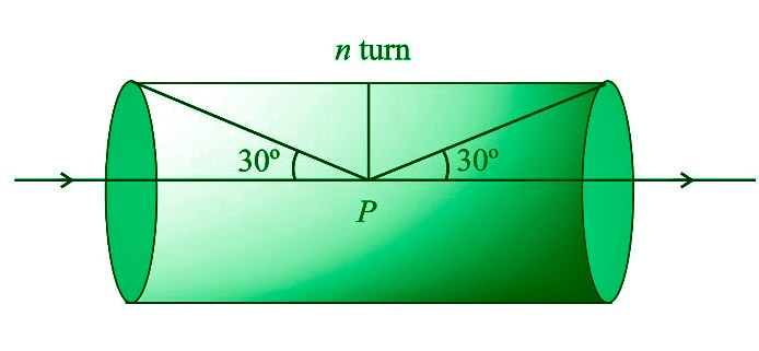
Problem 3: For the solenoid shown in the figure, what is the magnetic field at point P?
Solution:
B=μ0/4π x 2πni(sinα+sinβ)
From figure α=(90o–30o)=60o and β=(90o–60o)=30o
∴B=μ0ni/2 x (sin60o+sin30o)
=μ0ni/4(√3+1).
Problem 4: The figure shows the cross-sectional view of the hollow cylindrical conductor with inner radius R and outer radius 2R, a cylinder is carrying uniformly distributed current along its axis. What will be the magnetic induction at point P at a distance 3R/2 from the cylinder’s axis?
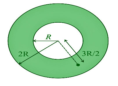
Solution:
By using B=μ0i/2πr x (r2–a2/b2–a2), here r=3R/2, a=R, b=2R
B=μ0i/2π(3R/2)×[(3R/2)–R2/(2R)2–R2]
=5⋅μ0i/36πr
Problem 5: What is the strength of the magnetic field at a location on the axis of an infinitely long, straight, thin-walled tube carrying current I?
Solution:
Because the tube is hollow on the inside and the Amperian loop does not carry any current, so magnetic field is zero.
Like Article
Suggest improvement
Share your thoughts in the comments
Please Login to comment...