Computer Graphics – Scan Line Algorithm in 3D (Hidden Surface Removal)
Last Updated :
14 Feb, 2021
This algorithm is based on the Image-space method and concept of coherence. As its name suggests itself Scan-line algorithm, so it processes one line at a time rather than processing one pixel(a point on raster display) at a time. The algorithm works as follows:
- Here each point at which the scan- line intersects the polygon surfaces are examined(processed) from left to right and in this process.
- The depth calculation (if there are overlapping surfaces found) is performed to identify the Hidden region(Visible surface) of the polygons which is nearer to the viewing plane.
- As soon as the visible surfaces(Hidden surfaces) are identified then the corresponding color-intensity values are updated into the refresh buffer(Frame buffer) if and only if the Flag of the corresponding surface is on.
- This algorithm works efficiently with one or more than one polygon surface and this algorithm is just an extension of the Scan line algorithm of Polygon filling.
Data Structure Used By Scan-Line Algorithm
Following data structure are used by the scan-line algorithm:
1. Edges list table(list): This list maintains the record of all the edges by storing their endpoint coordinates. The x-coordinate that we choose, whose Y-coordinate = Ymin.
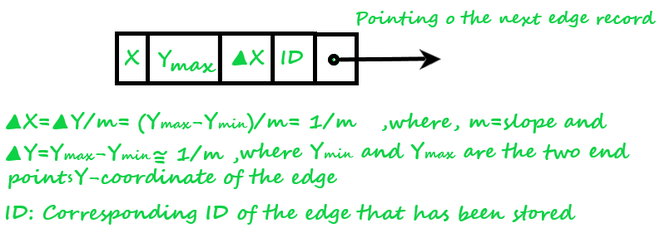
Fig.1
2. Active edges table(list): This table contains all those edges of the polygon that are intersected(crossed) by the current scan-line. The edges are dropped into the table in a sorted manner(Increasing value of x).
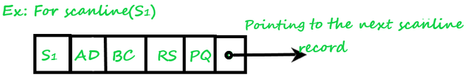
Fig.2
3. Polygon table(list): This list consists of:
- Polygon Id.
- Plane equation.
- Color Information of the surface.
- Flag of surface(on/off)].

Fig.3
Let’s understand more by the example as shown in the below in Fig.4 figure:
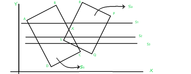
Fig.4
Here, two overlapped polygons are given which are intersected by three Scan-lines S1, S2, S3 respectively. So, What happens if the Scan-line algorithm is applied in order to identify the Hidden surface(visible surface)?
1. First, examine the scanline(S1), whose,
- Active edge table (Aet) contains: [AD,BC,RS,PQ], and
- The flag is set to “on” for surface(S1) and surface(S2) and the flag set “off” for the region between BX and RX as it’s an outer region of the polygon’s surface and not to be projected at view-port(display devices), now
- Drop the color-intensities of the corresponding surfaces into the frame buffer(refresh buffer).
2. Then, process the scanline(S2), whose,
- Active edge table (Aet) contains: [AD,BC,RS,PQ], and
- The flag is set to “on” for surface(ABCD) and surface(PQRS),
- Both of the polygons surfaces are overlapping each other so for this overlapped region which of the surface intensity should be taken into account? So to answer this calculates the depth(Zmin) of both surface(S1) and surface(S2) of this overlapped portion, next,
- If depth(S1)>depth(S2), then the Flag of surface S1=” on” and intensity of surface S1 will be considered else S2, now
- Drop the color-intensities of the corresponding surfaces whose flag is set to on into the frame buffer(refresh buffer).
3. As Scanline(S3) is passing through the same portion from where Scanline(S2) is passing, S3 also has the same Active edge table(Aet) components as S2 has and no need to calculate the depth(S1) and depth(S2) again so S3 can take the advantage of the concept of Coherence.
Note: Coherence is a concept that takes advantage of regularities and uniformities possessed by a scene.
Scan-Line Algorithm
- Initialize Edge table with all edges with their corresponding endpoints.
- Initialize Active edge table with all edges that are crossing by the current, scanline in sorted order(increasing order of x)
- Initialize a Polygon table with [Polygon Id, Plane equation, Color Information of the surface, Flag of surface(on/off)].
- Now, Repeat the following steps for all scanlines:
- Input corresponding values in Active edge list in sorted order using Y-coordinate as value.
- Scan the polygon until the Flag=”on” using and do color_intensity=background color.
- When one polygon’s Flag=”on”, then the corresponding polygon’s surface(Si) color intensity will be inserted into the frame buffer(refresh buffer).
- When two or more surfaced of polygons are overlapped and their Flag=”on” then find out the depth of that corresponding region of polygons surfaces, and set the Color_intensity=min[depth(S1), depth(S2)].
- Use the concept of Coherence for remaining planes.
Like Article
Suggest improvement
Share your thoughts in the comments
Please Login to comment...