Control Logic Gates in Computer Organization
Last Updated :
06 Apr, 2021
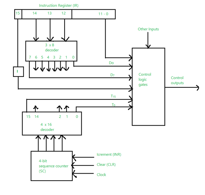
Control Logic Gates is the hardware component of a basic computer. It comprises some inputs and outputs. The diagram given below is related to the hardwired control organization.
The diagram below consists of the instruction register which has three parts: the I bit (15), the operation code (12, 13, 14), and bits 0 through 11. The symbols as D0 to D7 are the outputs. The symbol I is the flip flop which gets the instruction transferred from Bit 15 and the bits 0 through is applied to the control logic gate. The counter outputs are decoded into T0 through T15 which are the timing signals.
The bits 0 through 11 are put to the control logic gates.
Let’s see the inputs and outputs of the Control Logic gates.
The input of the control logic gate comes from:
- Two Decoders (One is 3 × 8 Decoder and another is 4 × 16 Decoder)
- I flip-flop
- Bits 0 through 11 of IR (Instruction Register)
Also, it consists of some other inputs:
- AC bits 0 through 15 to inspect (if AC = 0). It will also detect the sign bit in AC=15.
- DR bits 0 through 15 to inspect (if DR = 0).
- It also has the value of seven flip-flops.
Control Logic gate
Outputs of the control logic gate are:
- There are Signals to check the inputs of the nine registers
- There are Signals to check the read and write inputs of memory
- There are Signals to set, clear, or supplement the flip-flops
- The Signals S2, S1, and S0 are used to select a register for the bus
- The Signals to inspect the AC adder and logic circuit
Like Article
Suggest improvement
Share your thoughts in the comments
Please Login to comment...