Rigid bodies can move both in translation and rotation. As a result, in such circumstances, both the linear and angular velocities must be examined. To make these difficulties easier to understand, it is needed to separately define the translational and rotational motions of the body. The dynamics of the rotational motion of an item around a fixed axis will be discussed in this article. Given table list quantities associated with linear motion and their analogs in rotational motion.
Linear Motion
| Rotational Motion about a Fixed Axis
|
|---|
Displacement x
| Angular displacement θ
|
Velocity v = dx/dt
| Angular velocity ω = dθ/dt
|
Acceleration a = dv/dt
| Angular acceleration α = dω/dt
|
Mass M
| Moment of inertia I
|
Force F = Ma
| Torque τ = I α
|
Work dW = F ds
| Work W = τ dθ
|
Kinetic energy K = Mv2/2
| Kinetic energy K = Iω2/2
|
Power P = F v
| Power P = τω
|
Linear momentum p = Mv
| Angular momentum L = Iω
|
In rotational motion moment of inertia and torque play the same role as mass and force respectively in linear motion.
Rotational motion
The motion of a body in a circular path around a fixed point in space is known as rotational motion.
The motion of a body that does not deform or change shape in which all of its particles move in circles around an axis with a common angular velocity. For example the motion of the earth about its own axis, the motion of a wheel of vehicles, gears, motors, etc.
Rotational motion about a fixed axis
Because the axis is fixed, only torque components are considered that are in the same direction of the fixed axis. Only these components have the ability to rotate the body around its axis. A component of the torque that is perpendicular to the rotation axis will tend to turn the axis away from its current position. It is assumed that appropriate constraint forces will occur to cancel or cancel the influence of the perpendicular components of the (external) torques, allowing the axis to remain in its fixed position. As a result, the perpendicular components of the torques do not need to be considered. This means that for the calculation of torques on a rigid body:
- Only forces that are present in planes perpendicular to the axis need to be considered. Forces that are parallel to the axis produce torques that are perpendicular to the axis and do not need to be considered.
- Only the components of the position vectors that are perpendicular to the axis must be considered. Position vector components along the axis will result in torques perpendicular to the axis and do not need to be considered.
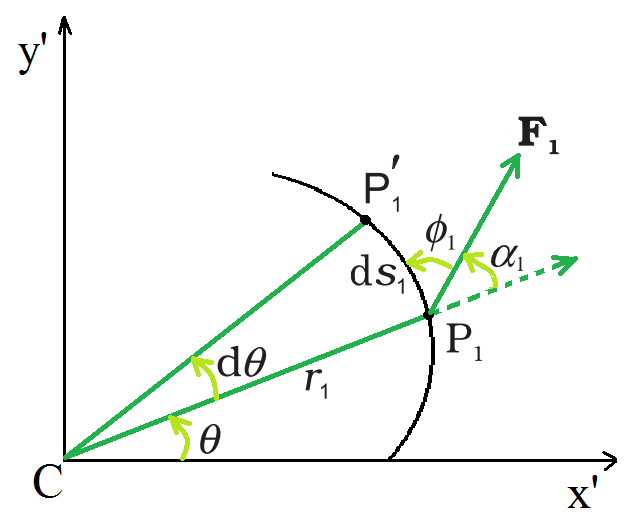
Work done by a force F1acting on a particle of a body rotating about a fixed axis; the particle describes a circular path with center C on the axis; arc P1P′1(ds1) gives the displacement of the particle
Rotational motion and work-energy principle
The figure depicts a cross-section of a rigid body rotating around a fixed axis, which is the z-axis (perpendicular to the page’s plane). As previously stated, only forces in planes perpendicular to the axis must be considered. Let F1 be an example of a typical force operating on a body particle at position P1 with its line of action perpendicular to the axis. Take the x′–y′ plane for convenience (coincident with the plane of the page). P1 represents a circular path with radius r1 and a center C on the axis; CP1 = r1. The point goes to location P1′ in time ∆t. As a result, the particle displaces ds1 has a magnitude of ds1 = r1dθ and a direction tangential at P1 to the circular route, as indicated. The particle’s angular displacement is given by dθ =∠P1CP1′.

where ∅1 is the angle between F1 and the tangent at P1, and α1 is the angle between F1 and the radius vector OP1 and ∅1+ α1= 90°.
OP1× F1 is the torque due to F1 about the origin. OP1 now equals OC + OP1, The torque generated by OC is not taken into account because it is along the axis. F1 produces an effective torque of τ1 = CP × F1 that is directed along the axis of rotation and has a magnitude of τ 1 = r1 F1 sinα.

If there are many forces acting on the body, the total work done on the body can be calculated by adding the work done by each of them. Using the numbers τ1, τ2,… to represent the magnitudes of the torques caused by various forces.

Although the forces that cause the torques to act on various particles, the angular displacement d is the same for all of them. Because all the torques are parallel to the fixed axis, the total torque magnitude is simply the algebraic sum of the torque magnitudes.
 ……………………………………(1)
Relationship between torque, moment of inertia, and angular acceleration
The work done by the total (external) torque acting on a spinning body around a fixed axis is given by this expression. Its similarity with the corresponding expression  for linear (translational) motion.
Dividing both sides of the above expression by dt,
 ……………………………..(2)
The above expression is for Instantaneous power. Compare this power formula for rotational motion around a fixed axis to power formula P = Fv for linear motion.
There is no internal motion in a perfectly rigid body. As a result, the work done by external torques is not dissipated and continues to raise the body’s kinetic energy. Equation (2) gives the rate at which work is done on the body. This is equated to the rate at which kinetic energy increases.

Equating rates of work done and of increase in kinetic energy,
 ……………………………………..(3)
The above expression is similar to Newton’s second law for linear motion expressed symbolically as F = ma. As the force causes acceleration, torque causes angular acceleration in a body. The applied torque determines the angular acceleration, which is inversely proportional to the body’s moment of inertia. For rotation along a fixed axis, the above expression is Newton’s second law.
Moment of Inertia
The moment of inertia is a measurement of an object’s resistance to rotational change. The moment of inertia is represented by I and is measured in kilograms per square meter (kgm2.) Its expressed as
I = Mr2
where m is the particle’s mass and r is the distance from the rotation axis.
Symmetric body with symmetric axis
| Moment of inertia
|
|---|
Ring
| 
|
Cylinder or disc
| 
|
Uniform sphere
| 
|
Rod with the axis through the end
| 
|
Rod with the axis at the center
| 
|
Sample problems
Problem 1: Give the location of the center of mass of a (i) sphere, (ii) cylinder, (iii) ring, and (iv) cube, each of uniform mass density. Does the center of mass of a body necessarily lie inside the body?
Solution:
Because the mass density is uniform in all four circumstances, the center of mass is positioned at their geometrical centers.
No, the center of mass of a body does not have to be located on the body. In a circular ring the center of mass is at the ring’s center, where there is no mass.
Problem 2: A cord of negligible mass is wound round the rim of a flywheel of mass 20 kg and radius 20 cm. A steady pull of 25 N is applied on the cord as shown in the given figure. The flywheel is mounted on a horizontal axle with frictionless bearings.
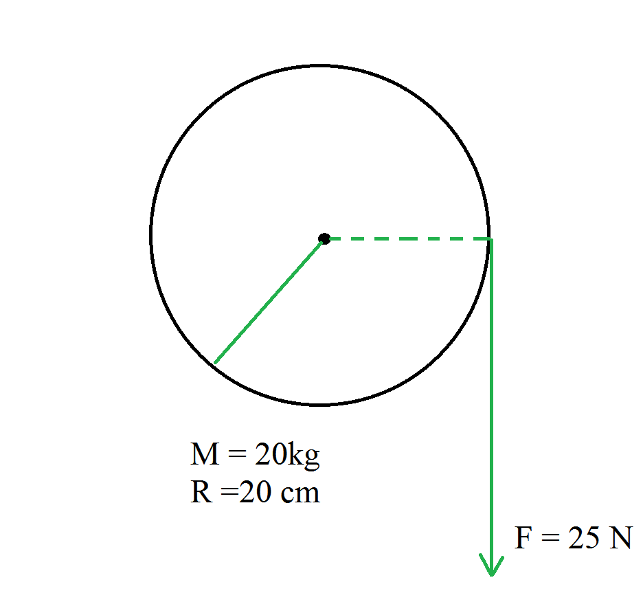
(a) Compute the angular acceleration of the wheel.
(b) Find the work done by the pull, when 2m of the cord is unwound.
Solution:
(a) Relationship between torque, moment of inertia, and angular acceleration is

Rearrange the expression,
 ………………………………………….(1)
The expression for the torque is
τ = F R
Substitute the values in the above expression,
τ = (25×0.20) Nm
τ = 5.0 Nm
The moment of inertia of flywheel about its axis is given by,
Substitute the values in the above expression,

Substitute the values in the expression (1),

(b) Work done by the pull unwinding 2m of the cord
W = 25 N × 2m = 50 J
Problem 3: A child sits stationary at one end of a long trolley moving uniformly with a speed V on a smooth horizontal floor. If the child gets up and runs about on the trolley in any manner, what is the speed of the CM of the (trolley + child) system? A child sits stationary at one end of a long trolley moving uniformly with a speed V on a smooth horizontal floor. If the child gets up and runs about on the trolley in any manner, what is the speed of the CM of the (trolley + child) system?
Solution:
When the child stands up and runs around on the trolley, the speed of the trolley’s and child’s center of mass remains constant, regardless of the child’s motion. It’s because the child and the trolley form a single system, and the forces at work are entirely internal. There is no change in the system’s momentum and velocity since there is no external force.
Problem 4: A car weighs 1800 kg. The distance between its front and back axles is 1.8 m. Its center of gravity is 1.05 m behind the front axle. Determine the force exerted by the level ground on each front wheel and each back wheel.
Solution:
Let F1 and F2 represent the forces that the level ground exerts on the front and back wheels, respectively. The rotational equilibrium about the front wheels is

Force on each back wheel is

The rotational equilibrium about the back wheels.

Force on each front wheel is

Problem 5: A solid cylinder of mass 20 kg rotates about its axis with angular speed 100 rad s-1. The radius of the cylinder is 0.25 m. What is the kinetic energy associated with the rotation of the cylinder? What is the magnitude of angular momentum of the cylinder about its axis?
Solution:
Given,
The mass of the solid cylinder is 20 kg.
The Angular speed is 100 rad s-1.
The moment of inertia of the solid cylinder about its axis is given by,
Substitute the values in the above expression,

The expression for the rotational kinetic energy is

Substitute the values in the above expression,

The expression for the angular momentum is

Substitute the values in the above expression,

Like Article
Suggest improvement
Share your thoughts in the comments
Please Login to comment...