Last Minute Notes – Computer Networks
Last Updated :
01 Mar, 2024
See Last Minute Notes on all subjects here.
- OSI Model
- Physical Layer
- Data Link layer
- Network Layer
- Transport Layer
- Presentation & Session layer
- Application Layer
OSI Model
OSI stands for Open Systems Interconnection. It has been developed by ISO– International Organization for Standardization, in the year 1984. It is a seven-layer architecture with each layer having specific functionality to perform.
OSI Layers, Data Units, and Functions:
| Layers |
Data Units |
Functions |
| Application Layer |
Data |
Mail Services, Directory Services, FTAM |
| Presentation Layer |
Data |
Encryption/Decryption, Compression |
| Session Layer |
Data |
Session Establishment, Synchronization, Dialog Controller |
| Transport Layer |
Segments, Datagram |
Segmentation |
| Network Layer |
Packets |
Traffic control, Fragmentation, Routing |
| Data Link Layer |
Frames |
Flow control, Error control, Access control |
| Physical Layer |
Bits |
Bit Synchronization, Bit rate control, Physical Topologies |
Layers and their uses:
Physical Layer
Network Topologies:
- Mesh Topology: In a mesh topology, every device is connected to another device via a particular channel. If suppose, N number of devices are connected with each other, then a total number of links is required to connect NC2.
- Bus Topology: Bus topology is a network type in which every computer and network device is connected to a single cable. If N devices are connected, then the number of cables required is 1 which is known as backbone cable, and N drop lines are required.
- Star Topology: In star topology, all the devices are connected to a single hub through a cable. If N devices are connected to each other, then the no. of cables required N.
- Ring Topology: In this topology, it forms a ring connecting devices with exactly two neighboring devices.
Transmission Modes:
- Simplex Mode: the communication is unidirectional, as on a one-way street. Only one of the two devices on a link can transmit, and the other can only receive.
- Half-duplex Mode: each station can both transmit and receive, but not at the same time.
- Full-duplex Mode: both stations can transmit and receive simultaneously.
Manchester Encoding: When there is a long sequence of 0s and 1s, there is a problem at the receiving end. The problem is that the synchronization is lost due to a lack of transmissions.
- NRZ-level encoding: The polarity of signals changes when the incoming signal changes from ‘1’ to ‘0’ or from ‘0’ to ‘1’. It considers the first bit of data as polarity change.
- NRZ-Inverted/ Differential encoding: In this, the transitions at the beginning of the bit interval are equal to 1 and if there is no transition at the beginning of the bit interval are equal to 0.
Data Link Layer
- Flow Control: The methods to maintain the flow of the data while the transmission is known as flow control methods. Mainly we have two approaches:
- Stop & Wait: Only one data packet can be shared over the link and the sender has to wait for the positive acknowledgment so that it can send another packet. It leads to poor efficiency and poor resource utilization.
- Sliding Window Protocol
- Go Back N: It is also known as “conservative protocol”, and uses cumulative/piggybacking acknowledgments. The receiver window size is 1, and the sender window size is 2k -1 where K is the number of bits received for the window size in the header.
- Selective Repeat: It accepts out-of-order packets and accepts cumulative/ independent/ piggybacking acknowledgments.

- Round Trip Time is the overall time taken in transmitting a packet, it is also known as minimum acknowledgment waiting time.
- Sequence Number <= (Sender’s Window Size) + (Receiver’s Window Size )
- Efficiency in TDM(polling) = Tt / (Tpoll + Tt)
- In CSMA/CD, Tt >= 2*Tp Hence, min frame length = 2*Tp*B and Efficiency in CSMA = 1/(1 + 6.44a)
- Back-off Algorithm for CSMA/CD Waiting time = back–off time Let n = collision number or re-transmission serial number. Then, Waiting time = K * Tslot where K = [0, 2n – 1 ]
- N = No. of stations Early Token Reinsertion : Efficiency = 1/(1 + a/N) Delayed Token Reinsertion : Efficiency = 1/(1 + (N+1)a/N)
- Pure Aloha Efficiency = 18.4 % Slotted Aloha Efficiency = 36.8%
- Maximum data rate (channel capacity) for noiseless and noisy channels
- Noiseless Channel: Nyquist Bit Rate BitRate = 2 * Bandwidth * log2(L) where L is the number of signal levels used to represent data.
- Noisy Channel : Shannon Capacity Capacity = bandwidth * log2(1 + SNR) where, SNR is the signal-to-noise ratio
- Error Control
- Hamming Code: It is a set of error-correction codes that can be used to detect and correct the errors that can occur when the data is moved or stored from the sender to the receiver.
- Redundant bits: 2r ≥ m + r + 1 where, r = redundant bit, m = data bit
- CRC: CRC stands for Cyclic Redundancy Check and this uses a polynomial generator on both the sender and receiver sides to detect the error in the transmitted data.
- Checksum: It is more reliable than other modes of error detection, it uses a checksum generator on the sender side and a checksum checker on the receiver side
- Framing in DLL: It provides a way for a sender to transmit a set of bits that are meaningful to the receiver.
- Character/Byte Stuffing: Used when frames consist of character. If data contains ED then, a byte is stuffed into the data to differentiate it from ED.
- Bit stuffing: Sender stuffs a bit to break the pattern i.e. here appends a 0 in data = 011101.
Network Layer
Class Full Addressing Table:
IPv4 header datagram:
IP version 6 Header Format:
Subnetting: Dividing a bigger network into a smaller network to maintain the security of the network is known as subnetting.
Supernetting: Multiple smaller networks are combined to form a bigger network. It is mainly used in router summarization, etc.
VLSM: Variable Length Subnet Mask is where the subnet design uses more than one mask in the same network which means more than one mask is used for different subnets of a single class A, B, C, or a network. It is also defined as the process of subnetting a subnet. It is used to increase the usability of subnets as they can be of variable size.
Internet Control Message Protocol: Since IP does not have an inbuilt mechanism for sending error and control messages. It depends on Internet Control Message Protocol(ICMP) to provide error control.
- Source quench message
- Parameter problem
- Time exceeded message
- Destination un-reachable
Difference between DVR and LSR:
- The router having the highest router priority will be declared as DR.
- If there is a tie-in router priority then the highest router will be considered. First, the highest loopback address is considered. If no loopback is configured then the highest active IP address on the router’s interface is considered.
Hop Count: Hop count is the number of routers between the source and destination network. The path with the lowest hop count is considered the best route to reach a network and therefore placed in the routing table.
The maximum hop count allowed for RIP is 15 and a hop count of 16 is considered as network unreachable.
Open shortest path first (OSPF): Open the shortest path first (OSPF) is a link-state routing protocol that is used to find the best path between the source and the destination router using its own SPF algorithm.
Designated Router(DR) and Backup Designated Router(BDR) election takes place in the broadcast network or multi-access network.
Routing Information Protocol (RIP): RIP is a dynamic routing protocol that uses hop count as a routing metric to find the best path between the source and the destination network. It is a distance vector routing protocol that has an AD value of 120 and works on the application layer of the OSI model. RIP uses port number 520.
Transport Layer
TCP header

In TCP congestion control Algorithm
- When Time Out Occurs Algorithm Enters Slow Start Phase
- When 3 Duplicate occurs algorithm enters the congestion avoidance phase
TCP 3-Way Handshake Process:
- Step 1 (SYN): In the first step, the client wants to establish a connection with the server, so it sends a segment with SYN(Synchronize Sequence Number) which informs the server that the client is likely to start communication and with what sequence number it starts segments with
- Step 2 (SYN + ACK): Server responds to the client request with SYN-ACK signal bits set. Acknowledgment (ACK) signifies the response of the segment it received and SYN signifies with what sequence number it is likely to start the segments with
- Step 3 (ACK): In the final part client acknowledges the response of the server and they both establish a reliable connection with which they will start eh actual data transfer.
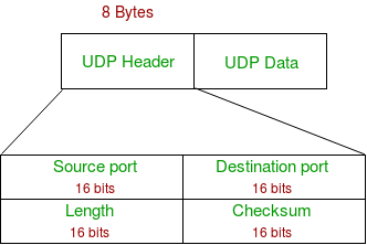
UDP header:
Session & Presentation Layer
Session Layer:
- The session layer is responsible for establishing, maintaining, and terminating sessions in a network. The session layer manages data transmission for a certain time period.
- The session layer is responsible for the identification of entities participating in a session.
- It provides synchronization services to the data stream.
Presentation Layer:
- The presentation layer translates the data packet from the network layer to the application layer and vice versa.
- The main responsibility of the Presentation layer is protocol conversion, data encryption/decryption, character conversion, and data compression.
- It sets standards for different systems to provide flawless communication.
Application Layer
Application Layer: It is the topmost layer of the OSI model and it directly interacts with web applications or application services. This layer provides several ways for manipulating the data (information) which actually enables any type of user to access the network with ease.
Functions of Application Layer:
- Application Layer facilitates email sending and storing features.
- This layer allows users to access, retrieve and manage files from a remote computer.
- This layer provides services that include: E-mail, File transfer, directory services, network resources, etc.
Domain Name Server: DNS is a hostname for IP address translation service. DNS is a distributed database implemented in a hierarchy of name servers. It is an application layer protocol for message exchange between clients and servers.
Protocols in Application Layer
- Dynamic Host Configuration Protocol(DHCP) is an application layer protocol that is used to provide:
- Subnet Mask (Option 1 – e.g., 255.255.255.0)
- Router Address (Option 3 – e.g., 192.168.1.1)
- DNS Address (Option 6 – e.g., 8.8.8.8)
- Vendor Class Identifier (Option 43 – e.g., ‘unifi’ = 192.168.1.9 ##where unifi = controller)
- Simple Network Management Protocol (SNMP): SNMP is an application layer protocol that uses UDP port number 161/162.SNMP is used to monitor networks, detect network faults, and sometimes even used to configure remote devices.
- Simple Mail Transfer Protocol (SMTP): SMTP is an application layer protocol. The client who wants to send the mail opens a TCP connection to the SMTP server and then sends the mail across the connection. The SMTP server is always in listening mode. As soon as it listens for a TCP connection from any client, the SMTP process initiates a connection on that port (25). After successfully establishing the TCP connection the client process sends the mail instantly.
- File Transfer Protocol (FTP): File Transfer Protocol(FTP) is an application layer protocol that moves files between local and remote file systems. It runs on top of TCP, like HTTP. To transfer a file, 2 TCP connections are used by FTP in parallel: control connection and data connection.
- Hypertext Transfer Protocol (HTTP): is an application-level protocol that uses TCP as an underlying transport and typically runs on port 80. HTTP is a stateless protocol i.e. server maintains no information about past client requests.
Port number and transport mode used by Protocols:
| Port Number |
TCP/UDP |
Protocol Name |
| 20, 21 |
TCP |
File Transfer Protocol (FTP) |
| 22 |
TCP and UDP |
Secure Shell (SSH) |
| 23 |
TCP |
Telnet |
| 25 |
TCP |
Simple Mail Transfer Protocol (SMTP) |
| 53 |
TCP and UDP |
Domain Name Server (DNS) |
| 67, 68 |
UDP |
Dynamic Host Configuration Protocol (DHCP) |
| 69 |
UDP |
Trivial File Transfer Protocol (TFTP) |
| 80 |
TCP |
HyperText Transfer Protocol (HTTP) |
| 110 |
TCP |
Post Office Protocol (POP3) |
| 119 |
TCP |
Network News Transport Protocol (NNTP) |
| 123 |
UDP |
Network Time Protocol (NTP) |
| 135-139 |
TCP and UDP |
NetBIOS |
| 143 |
TCP and UDP |
Internet Message Access Protocol (IMAP4) |
| 161, 162 |
TCP and UDP |
Simple Network Management Protocol (SNMP) |
| 179 |
TCP |
Border Gateway Protocol (BGP) |
| 389 |
TCP and UDP |
Lightweight Directory Access Protocol |
| 443 |
TCP and UDP |
HTTP with Secure Sockets Layer (SSL) |
| 500 |
UDP |
Internet Security Association and Key Management Protocol (ISAKMP) / Internet Key Exchange (IKE) |
| 636 |
TCP and UDP |
Lightweight Directory Access Protocol over TLS/SSL (LDAPS |
| 989/990 |
TCP |
FTP over TLS/SSL |
Like Article
Suggest improvement
Share your thoughts in the comments
Please Login to comment...