Ohm’s Law was given by German physicist Georg Simon Ohm. It states the relationship between current, resistance, and voltage across an electrical circuit. This relationship between current I, voltage V, and resistance R was given by famous German scientist Georg Simon Ohm in 1827. He found conducting his experiment that the product of the current flowing through the conductor and the resistance of the conductor determines the voltage drop over that conductor in the circuit.
In this article, we will explore the concept of Ohm’s Law in detail including all the topics mentioned in the following table of content.
Ohm’s Law Definition
Ohm’s law states that the voltage across a conductor is directly proportional to the current flowing through it, provided all physical conditions and temperatures remain constant.
Hence, according to Ohm’s Law, the current flowing through the conductor is directly proportional to the voltage across the circuit, i.e. V ∝ I. Thus, as Ohm’s Law provides the basic relation between the voltage applied and current through the conductor, it is considered as the basic law which helps us in dealing electric circuit. Ohm’s Law states that the current follows a linear relationship with voltage.
Ohm’s Law Explanation
Ohm’s Law is one of the fundamental laws of electrostatics which state that, the voltage across any conductor is directly proportional to the current flowing in that conductor. We can define this condition as,
V ∝ I
Removing the proportionality sign,
V = RI
where R is the proportionality constant and is called the Resistance of the material. The resistance of the material is calculated as,
R = V/I
Resistance is measured in Ohms. It is denoted by the symbol Ω.
Ohm’s Law Formula
Under the condition that all physical parameters and temperatures remain constant, Ohm’s law states that the voltage across a conductor is directly proportional to the current flowing through it.
Ohm’s Law is stated as:
V ∝ I
OR
V = I × R
Where,
- R is the Constant of Proportionality known as Resistance,
- V is the Voltage applied, and
- I is the current flowing through the electrical circuit.
The above formula can be rearranged to calculate current and resistance also, as follows:
According to Ohm’s Law, the current flowing through the conductor is,
I = V / R
Similarly, resistance can be defined as,
R = V / I
Ohm’s Law Graph
Ohm’s Law holds good when physical conditions like temperature and others are constant. This is because of the fact that the current flowing through the circuit varies by changing the temperature. Therefore, in such cases when physical factors like temperature come into play, Ohm’s law violates. For example, in the case of a Light bulb, where temperature increases when the current flowing through it rises. Here, Ohm’s Law doesn’t follow.
The graph for an ohmic circuit is discussed in the image below,
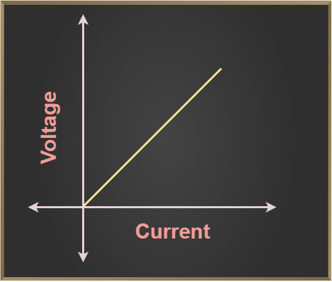
Ohms Law Graph
Ohm’s Law Unit
There are three physical quantities that are associated with the Ohms Law that include,
The table added below shows the various symbol and their unit used.
Physical Quantity
| Unit of Measurement
| Unit Abbreviation
|
|---|
Current(C)
| Ampere
| A
|
Voltage(V)
| Volt
| V
|
Resistance(R)
| Ohm
| Ω
|
Ohm’s Law Equations
Ohm’s law provides three equations which are:
- V = I × R
- I = V / R
- R = V / I
Where,
- V is the voltage,
- I is the current, and
- R is the resistance.
Relationship between Voltage, Current, and Resistance : Ohm’s Law
The relation between voltage, current, and resistance can easily be studied using the formula,
V = IR
Where,
- V is the voltage,
- I is the resistance, and
- R is the resistance.
We can study this formula with the help of the table discussed below,
Voltage
| Current
| Resistance
|
|---|
2 V
| 1/2 A
| 4 Ω
|
4 V
| 1 A
| 4 Ω
|
8 V
| 2 A
| 4 Ω
|
Ohm’s Law Triangle
Ohm’s Law Triangle is a visual representation for understanding and learning the Ohm’s Law relation between voltage, current, and resistance. This tool help helps engineers to remember the order of the relationship between the three main aspects: current (I), voltage (V), and resistance (R).
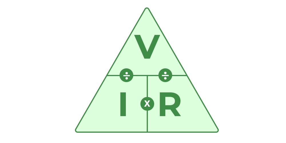
Ohms Law Triangle
Vector Form of Ohm’s Law
The relation between current and voltage is established by, Ohm’s law, and its vector form is,

Where,
 is Current Density vector,
 is Electric Field vector, and
 - σ is conductivity of material.
Resistivity
The hindrance faced by the electrons while moving in any material is called the resistivity of the material.
Let a resistor of a length of ‘l’ and the cross-sectional area of ‘A’ has a resistance be R. Then we know,
Resistance is directly proportional to the length of the resistor, i.e. R ∝ l, . . .(1)
Resistance is inversely proportional to the cross-section area of the resistor, i.e. R ∝ 1/A . . .(2)
combining eq. (1) and eq.(2)
R = ρl / A
Where ρ is the proportionality constant called coefficient of resistance or resistivity.
Now if L = 1m and A = 1 m2, in the above formula we get,
R = ρ
This means for a resistor of length 1 m and cross-section area 1 m2 the resistance is called the resistivity of the material.
Experimental Verification of Ohm’s Law
Verification of Ohm’s Law is achieved by performing the following experiment.
Apparatus Required
The apparatus required for performing the experiment for the Verification of Ohm’s Law is,
- Resistor
- Ammeter
- Voltmeter
- Battery
- Plug Key
- Rheostat
Circuit Diagram
The circuit diagram for the Experimental Verification of Ohm’s Law is given in the diagram below,
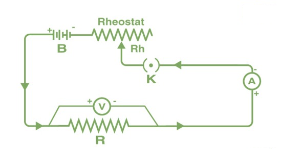
Circuit Diagram of Ohms Law
Procedure
The procedure for experimental verification of Ohm’s Law is mentioned below:
- The key K is closed initially and the rheostat is adjusted such that the reading in ammeter A and voltmeter V is minimum.
- The current is then increased in the circuit by adjusting the rheostat, and the current at various values of the rheostat and their respective voltage is recorded.
- Now for different values of voltage(V) and current(I) and then calculate the ratio of V/I.
- After calculating all the ratios of V/I for different values of voltage and current, we notice that the value is almost constant.
- Now plotting a graph of the current against the potential difference we get a straight line. This shows that the current is directly proportional to the potential difference and its slope is the resistance of the wire.
Ohm’s Law Pie Chart
To better understand the relationship between various parameters, we can take all the equations used to find the voltage, current, resistance, and power, and condense them into a simple Ohm’s Law pie chart as shown below:
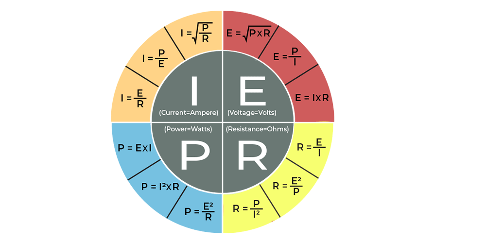
Ohms Law Pie Chart
Ohm’s Law Matrix Table
Like Ohm’s Law Pie Chart shown above, we can condense the individual Ohm’s Law equations into a simple matrix table as shown below for easy reference when calculating an unknown value.
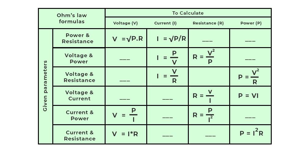
Ohms Law Matrix Table
Applications of Ohm’s Law
When the other two numbers are known, Ohm’s law may be used to determine the voltage, current, impedance, or resistance of a linear electric circuit.
Main applications of Ohm’s Law:
- It also simplifies power calculations.
- To keep the desired voltage drop between the electrical components, Ohm’s law is employed.
- An electric circuit’s voltage, resistance, or current must be determined.
- Ohm’s law is also utilized to redirect current in DC ammeters and other DC shunts.
How to Establish a Current-Voltage Relationship?
The ratio V ⁄ I remains constant for a given resistance while establishing the current-voltage connection, hence a graph of the potential difference (V) and current (I) must be a straight line.
How can we discover the unknown resistance values?
The constant ratio is what determines the unknown resistance values. The resistance of a wire with a uniform cross-section relies on the length (L) and the cross-section area (A). It also relies on the conductor’s temperature.
The resistance, at a given temperature,
R = ρ L ⁄ A
where,
ρ is the specific resistance or resistivity and is the wire material’s characteristic.
The wire material’s specific resistance or resistivity is,
ρ = R A ⁄ L
Calculating Electrical Power using Ohm’s Law
We define electric power as the power required by electric charges to do various works. The rate of consuming electric energy is called electric power. The unit of measuring electric power is the watt. Using the Ohm’s law we can easily find the power of the electric circuit. The formula to calculate the electric power is,
P = VI
Where,
- P is the power of the circuit,
- V is the voltage across the circuit, and
- I is the current passing through the circuit.
We know that, using Ohm’s Law,
V = IR
Using the power formula we get,
P = V2/R
P = I2R
Limitations of Ohms Law
Various limitations of the Ohms law are,
- The law of Ohm does not apply to unilateral networks. The current can only flow in one direction in unilateral networks. Diodes, transistors, and other electronic components are used in these sorts of networks.
- Non-linear components are also exempt from Ohm’s law. Non-linear components have a current that is not proportional to the applied voltage, which implies that the resistance value of those elements varies depending on the voltage and current. The thyristor is an example of a non-linear element.
Analogies of Ohm’s Law
There are various analogies given in the past to explain Ohm’s Law, some of the most common analogies are:
- Water Pipe Analogy
- Temperature Analogy
Let’s discuss these analogies in detail.
Water Pipe Analogy for Ohm’s Law
We know that the current passing through any circuit depends on the voltage applied and the resistance of the circuit. But we can see the current flowing through the circuit, to understand it better we use the Water Pipe Analogy in which the flowing water represents the current and we can understand Ohm’s law using this concept.
Water flowing through the pipes is similar to the current flowing through the electric circuit. We know that in an electric circuit, Voltage is required to move the current in the circuit in the same way Pressure in the water pipe system allows the water to flow easily in the system.
If the pressure is increased more water flows through the pipe which resembles Ohm’s law that state if the voltage is increased, more current flows through the electric Circuit.
Temperature Analogy
Similarly, a temperature circuit can also be compared to an ohmic conductor. Here, temperature gradient works similarly to voltage, and heat flow works similarly to current.
Read More,
Solved Examples on Ohm’s Law
Example 1: Find the resistance of an electrical circuit with a voltage supply of 15 V and a current of 3 mA.
Solution:
Given:
V = 15 V,
I = 3 mA = 0.003 A
The resistance of an electrical circuit is given as:
⇒ R = V / I
⇒ R = 15 V / 0.003 A
⇒ R = 5000 Ω
⇒ R = 5 kΩ
Hence, the resistance of an electrical circuit is 5 kΩ.
Example 2: If the resistance of an electric iron is 10 Ω and a current of 6 A flows through the resistance. Find the voltage between two points.
Solution:
Given:
I = 6 A, R = 10 Ω
The formula to calculate the voltage is given as:
V = I × R
⇒ V = 6 A × 10 Ω
⇒ V = 60 V
Hence, the voltage between two points is 60 V.
Example 3: Find the current passing through the conductor drawing 20 volts when the power drawn by it is 60 watts.
Solution:
According to Ohm’s P = VI
Given P = 60 watt, V = 20 volt
⇒ I = P/V
⇒ I = 60/20
⇒ I = 3 A
Hence, the current flowing through the conductor is 3 A
Example 4: A battery of 6 V is connected to the bulb of resistance 4 Ω. Find the current passing through the bulb and the circuit’s power.
Solution:
Given,
V = 6 V
R = 4 Ω
We know that,
V = IR (Ohms Law)
⇒ 6 = 4R
⇒ I = 6 ÷ 4 = 1.5 A
⇒ I = 1.5 A
Thus, the current flowing through the bulb is 1.5 A
For the Power of the circuit
P = VI
⇒ P = (6)(1.5)
⇒ P = 9 watt
Thus, the power of the circuit is 9 watts.
FAQs on Ohm’s Law
Q1: What is Ohm’s Law?
Answer:
According to Ohm’s Law the current passing through the conductor is directly proportional to the potential difference across the end on the conductor, if temperature and the other physical conditions doesn’t changes.
Q2: Who discovered Ohm’s Law?
Answer:
The German physicist Georg Simon Ohm was the first to explain Ohm’s Law. He stated that the current passing through the conductor is directly proportional to the voltage applied.
Q3: Is Ohm’s Law universally applicable?
Answer:
No Ohm’s law is not a universal law as it is not applicable to all electric circuits.
- The circuits which obey Ohm’s Law are called Ohmic Circuit
- The circuits which do not obey Ohm’s Law are called Non-Ohmic Circuit
Q4: When was Ohm’s Law Discovered?
Answer:
Ohm’s law was first stated by Georg Simon Ohm in his book Die Galvanische Kette, Mathematisch Bearbeitet in the year 1827.
Q5: What is the unit of Resistance?
Answer:
The SI unit of resistance is Ohm. It is denoted by Ω.
Q6: What is the Dimensional Formula for Resistance?
Answer:
Dimensional formula for resistance is [M1L2T-3I-2]
Q7: Why doesn’t Ohm’s Law apply to semiconductors?
Answer:
Semiconducting devices are nonlinear in nature due to which Ohm’s law does not apply to them. This indicates that the voltage-to-current ratio does not remain constant when voltage varies.
Q8: When does Ohm’s law fail?
Answer:
The behavior of semiconductors and unilateral devices like diodes defines Ohm’s law. If physical factors such as temperature and pressure are not kept constant, Ohm’s law may not provide the intended effects.
Like Article
Suggest improvement
Share your thoughts in the comments
Please Login to comment...