Operational Amplifier (op-amp) in Digital Electronics
Last Updated :
10 Feb, 2021
An amplifier is a device that increases the strength of the input signal. It can be Voltage amplifiers, whose input is some voltage and output is also voltage but amplified. Current amplifier, whose input is some current and output is also current but amplified.
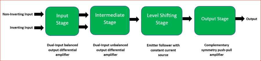
Block diagram of an op-amp
- Transconductance amplifier, whose input is some voltage and output is the current.
- Transimpedance amplifier, whose input is some current and output is the voltage.
An operational amplifier (or, op-amp) is a voltage amplification, three-terminal electronic device, having two input terminals namely Inverting terminal (marked by ‘-‘ sign in diagrams) and a Non-inverting terminal(marked by ‘+’ sign in diagrams), and the third terminal is the output terminal. Gain (“A”) of the op-amp = output signal/input signal
Different configurations of op-amp:
Open Loop Configuration –
In this configuration, the op-amp does not have any feedback. Ideally, it has an infinite open-loop gain(practically hundreds of thousands of times larger than the potential difference between its input terminals).
#Inverting Mode:
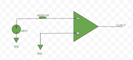
Inverting open loop op-amp
#Non-inverting Mode:

Non-inverting open loop op-amp
Closed Loop Configuration –
In this configuration of the op-amp, negative feedback is used i.e., a portion of the output voltage is applied back to the inverting input. This feedback greatly reduces the gain of the op-amp as compared to open-loop gain. Thus, it is a kind of controlled way of amplification.
#Inverting Mode:
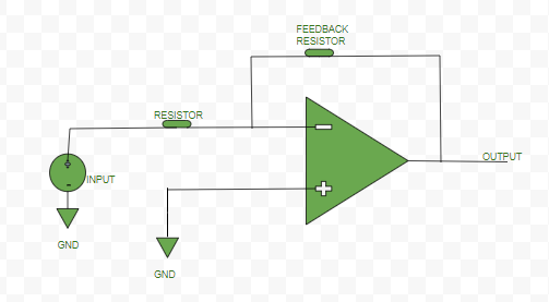
Inverting closed loop op-amp
#Non-inverting Mode:

Non-inverting closed loop op-amp
Characteristic of an ideal op-amp –
- Open Loop gain: Ideally op-amp should have an infinite open-loop gain (practically it is hundreds of thousands of times larger than the potential difference between its input terminals).
- Input impedance or resistance: Ideally op-amp should have infinite input resistance (practically it should be very high).
- Output impedance or resistance: Ideally op-amp should have zero output resistance (practically it should be very low).
- Bandwidth: Ideally op-amp should have infinite bandwidth (practically it is limited).
- CMRR: Ideally op-amp should have infinite CMRR, Common Mode Rejection Ratio so that common noise voltage in the output becomes zero.
- Slew Rate: Ideally op-amp should have infinite SR, slew rate so that any change in the input voltage simultaneously changes the output voltage.
Basic terminologies of an op-amp –
1. Slew Rate: The Slew rate (SR) of an op-amp is defined as the maximum rate of change of output voltage per unit of time. It is represented as volts per microsecond ( V/μs).
SR = (dVo / dt) |max
2. Output Offset Voltage: Output of the op-amp should be ideally zero when the voltage difference between the inputs is zero but, practically the output is non-zero, there is a voltage of very small magnitude. This unwanted voltage at the output side when no input is given is called Output Offset Voltage.
3. Input Offset Current: Magnitude of the difference of current entering inverting and non-inverting terminals, when no input voltage is given to op-amp.
Io = |Ib1-Ib2|;
Io-Input Offset Current, Ib1 &
Ib2-current at input terminals
4. Input Bias Current:
I(bias) = (Ib1+Ib2)/2
5. Input Offset Voltage: It is the voltage applied deliberately either at inverting or non-inverting terminal of an op-amp to nullify the effect of Output Offset Voltage.
 V(Input Offset Voltage) = 0 (ideally)
V(Input Offset Voltage) = -V(Output Offset Voltage) (practically)
6. Common Mode Rejection Ratio (CMRR): It is the ratio between the differential mode gain (when the different signals are applied to both inputs terminals) to the common-mode gain(when the signal is applied to just one of the input terminals).
CMRR = |(differential mode gain) / (common mode gain)|
7. Supply Voltage Rejection Ratio (SVRR): It is defined as the ratio of change in input offset voltage, Vio of an op-amp to change in the supply voltage, V.
SVRR = ΔVio / ΔV
Application – It can be used as:
- Inverting and Non-inverting adder,
- Subtractor,
- Integrator,
- Differentiator,
- Logarithmic amplifier etc.
Like Article
Suggest improvement
Share your thoughts in the comments
Please Login to comment...