Charges are present in every living and non-living being on earth. In earlier centuries, charges were considered to be rest. But in the 19th century, a new phenomenon was observed about moving charges. It was observed that moving charges constitute a current. These currents occur in many situations in nature, for example – a lightning strike is actually a current that flows from clouds up to the ground. In everyday lives, people encounter current in many electric devices.
Electric Current
The devices in our everyday use carry electric currents inside of them. Torches, bulbs, fans, heaters, etc are some examples of electric devices which have electric currents flowing into them. Let’s imagine charges are flowing in the horizontal direction, in this flow assume a surface with a small area held normal to the direction of flow of charges. Assume both positive and negative charges are flowing across this area.
In a given time interval “t”, the charge passing through the surface can be divided into two parts – positive charges and negative charges. Let’s say q+ is the net positive charge passing through the surface in the given time interval, similarly q– is the net negative charge passing through the surface in the given time interval. In this case, the net charge passing through this surface in this interval will be,
qnet = q+ – q–
Electric current in defined as the rate of flow of charge in a conductor.
In this case, the average current flowing through the given surface in time “t” is given by,

Here, I represent the average current flowing through the surface.
The unit for current is Ampere (A), Ampere stands for Column/sec.
In case when the rate of flow of charge is varying, the current flowing is given by,

⇒ 
Resistance
Water flowing through a pipe encounters resistance to its flow if the current is considered as water and the pipe is considered to be the conductor through which the current is flowing. The same analogy can be used to deduce the obstruction of flow in the case of current too. This obstruction of flow against the current is termed Resistance. The resistance in a wire experiencing a current I and voltage V is defined as,
R = V/I
Here, R denotes the resistance of the wire. Its unit is “ohms” which is denoted by Ω
Notice in the relation, the resistance depends inversely on the current flowing through the wire. Thus, the more the resistance of the wire, the less is the current flowing through it, which can also be deduced from the intuitive definition of the resistance.
V-I Characteristics
The V-I characteristics of a circuit stand for the Voltage-Current characteristics of a circuit. The graph of current and voltage is drawn on the graph to show how one changes when a change in the other is done. The slope of this graph gives resistance, but only in the case when the slope is linear. Does that mean non-linear graphs of V-I characteristics are present too? YES. There are both linear and non-linear graphs. However, if non-linear graphs exist, ohms law would not have been valid. Ohms law exists and so does the non-linear graph.
The reason behind this so-called contradiction is simple. Although Ohms law is applicable and true for a lot of materials, it is not applicable for some materials where the law of proportionality does not work. Let’s learn about each one of the graphs in detail,
Linear V-I Characteristics
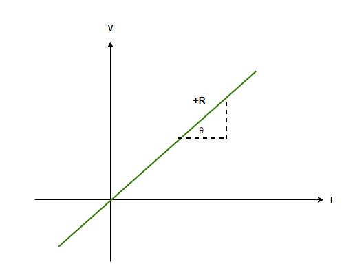
Linear V-I characteristics are shown by ohmic resistors. Ohms law talks about the relation between voltage and current where it tells that the voltage and current are proportional to each other, therefore, if a graph is drawn, a straight line is obtained. The slope of the line gives resistance. Higher the slope, the higher will be the resistance. Hence,
 and R = tanθ
The V-I characteristics give a straight line passing through the origin. In a resistance, if the voltage polarity is reversed, the current will start to flow opposite direction with equal magnitude if the magnitude of the voltage is not altered.
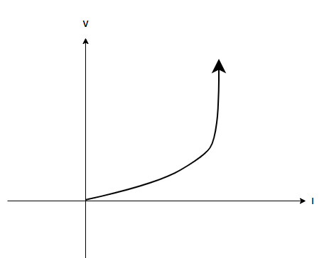
Non-Linear V-I Characteristics
If the non-linear V-I characteristics exist, which they do, the resistance must show a different property. It is correct that if the V-I graph is not linear, the resistance is not constant and it depends either on voltage or current. Examples of non-ohmic resistances are diodes, SCRs (Silicon controlled resistors), transistors, etc. These are the noticeable changes that are seen in non-linear graphs,
- Voltage is no more proportional to current.
- The relationship existing between voltage and current depends upon voltage. If the voltage is reversed without changing the magnitude, the current will become opposite but the magnitude will change.
- The relationship between V and I is not unique, which means, more than one value of voltage is obtained for one value of current.
Sample Problems
Question 1: A battery of 10 Volts connected to a conductor induces a current of 10mA in the conductor. Find the resistance of the conductor.
Answer:
The resistance of conductor is given by the relation,
R = V/I
Given:
V = 10V
I = 10mA = 0.01 A
Plugging in the values inside the relation,
R = V/I
⇒ R = (10)/(0.01)
⇒ R= 1000 Ohms.
Question 2: A battery of 200 Volts connected to a material induces a current of 0mA in the conductor. Find the resistance of the conductor.
Answer:
The resistance of conductor is given by the relation,
R = V/I
Given:
V = 200V
I = 0mA = 0 A
Plugging in the values inside the relation,
R = V/I
⇒ R = (200)/(0)
The resistance is closes to infinity, which means the material is an insulator.
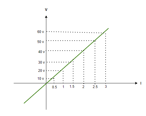
Question 3: Determine the resistance from the linear graph shown below,
Solution:
In order to find the resistance from the V-I graph, the easiest way is to simply find the slope,
Take any x axis value (current value) and its relative y axis value (voltage), and then take their ratio to find the resistance,
R = 10/0.5 = 20Ω
R = 20/1 = 20Ω
R = 30/1.5 = 20Ω
Hence, finding slope from anywhere will provide one value of resistance, that is, 20Ω.
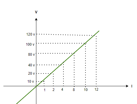
Question 4: Determine the resistance from the linear graph shown below,
Solution:
In order to find the resistance from the V-I graph, the easiest way is to simply find the slope,
Take any x axis value (current value) and its relative y axis value (voltage), and then take their ratio to find the resistance,
R = 10/1 = 10Ω
R = 20/2 = 10Ω
R = 40/4 = 10Ω
Hence, finding slope from anywhere will provide one value of resistance, that is, 10Ω.
Question 5: Identify which of the three regions is the negative resistance region from the below-given graph,
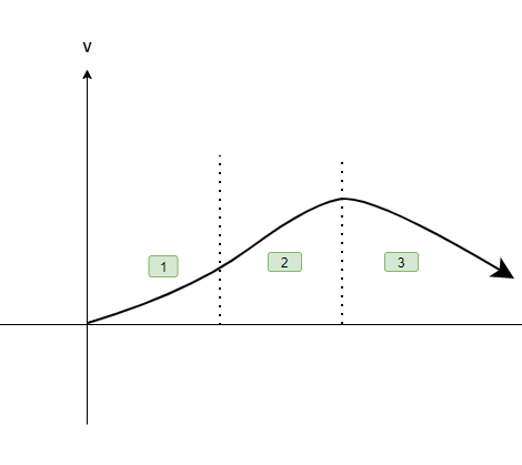
Answer:
Negative resistance region is that region in which the slope of the graph becomes negative. Let’s observe the three regions and identify the negative region,
- Region 1 is the positive resistance region as the slope is positive and the region is clearly seen to be the ohmic region.
- Region 2 is the positive resistance region again, even though it is non-linear in nature, the graph is not going down and hence, the slope positive.
- Region 3 is the negative region as the graph in this region is going down making the slope negative.
Like Article
Suggest improvement
Share your thoughts in the comments
Please Login to comment...